Rename this file as Chapter_2_Assignment_TurnIn.sagews
To do this, go to the file menu (click
Filesabove), then click
Worked Example
I will work through example 2.1 on page 23 in your text to show you how you can make use of SageMath

1) Facts
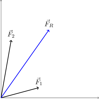
This is the first part of the problem solving format. Since there is already a sketch of the problem above we don't need to include the sketch like we normally would.
Known quantities oriented at an angle counterclockwise from the x-axis is oriented at an angle clockwise from the y-axis.
Question Find the magnitude and direction of the resultant force on the hook by the two forces
2) Lacking
We are lacking the resultant force . We need the magnitude and direction of this force.
3) Approximations and Assumptions
This problem is pretty straight forward so no assumptions or approximations are needed.
4) Representations
The free body diagrams below are the visual representations needed to solve this problem.
Free Body Diagrams
To draw the free body diagram (which is included in this example but I wanted to show you how it's done) we will use Latex with a package called Tikz. All solutions must include a free body diagram of some sort.
You can draw a neatly sketched free body diagram by hand, take a picture, upload it to SageMath, and insert it in your homework or you can draw the free body diagram in SageMath using Tikz. I recommend drawing it in SageMath because being able to use Latex is an impressive skill to have on your resume, but I will leave the final choice up to you. You are not required to use Tikz if you don't want. I will be using Tikz and Latex so you can use my code as a template. You can find a tutorial for getting started with Tikz at http://cremeronline.com/LaTeX/minimaltikz.pdf
Upload and insert hand-drawn free body diagrams
Upload the file into your homework directory
Go to the file directory and select the
+Createbutton, then drag and drop your picture to the upload boxInsert the following code into your worksheet, replacing filename with the actual name of the file including the extension:
<img src="filename" width="600">Adjust the width so the image is big enough to see clearly.
Draw free body diagrams in SageMath
There is a Handout folder on 'How to insert free body diagrams in SageMathCloud' that covers how to use Tikz to draw figures. Go there is you want to use Tikz for these drawings.
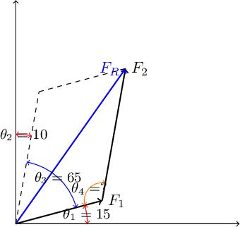
The sum of the angles inside a closed parallelogram must add up to (A simple case of this is a rectangle, which has four angles).
Since and the angle opposite both equal , we can find from the following: or
We'll use the law of sines and law of cosines in the cell below to find out the magnitude and direction of .
5) Solve Problem
Below is the math used to find the resultant force
Summary
The magnitude of the resultant force is directed at an angle of above the x-axis.
6) Evaluate the answer
Is this answer reasonable?
The two forces we are adding together are 100 N and 150 N. We expect the magnitude of to be larger than either magntidue (so ) and smaller than the sum of the two (so ). Our result of 213 N falls in between the two limits so this result is reasonable.
The angle of is most likely between the angle both vectors make with the x-axis ( and ). The result of falls between the two values so this is a reasonable angle.
The result of passes two reasonability tests so I feel confident this answer is reasonable.
 Problem 1
The first problem is example 2.2 from the text so the problem is worked for you. This is good practice for using SageMath to write up your solutions. 
Write up the first several steps of the problem solving format, which include 1) Facts, 2) Lacking Information, and 3) Approximations and Assumptions (none needed now).
For part (4) of the problem solving format, Representations, draw a free body diagram. Redraw figure (b) below. I've given you a template for this below if you want to use Tikz. Skip figure (c) for now. If you want to draw the free body diagram and insert a picture, create a markdown cell (start the cell with
%md), and use<img src="filename" width="600">. Replace filename with the name of your photo and adjust the width so the free body diagram is easily readable.Describe how you are going to solve the problem. Don't just copy the text from the text. Try paraphrasing in your own words. This is good practice. Use a markdown cell for this. I've included a rough template below.
Write up your calculations using SageMath. Include all equations and use comments to explain your steps.
Summarize and Evaluate your result by answering "Is this answer reasonable?" Use a markdown cell. I've included a rough template for this.
Your explanation of the problem here
5) Solve
Insert code for calculating the answer below
Summary
Place your summary of your answers here
Evaluate Answer:
Write a credible argument as to why your results are reasonable.
Is this answer reasonable?
Problem 2

Resolve each force acting on the gusset plate into its x and y components, and express each force as a Cartesian vector
Note: vectors (including i, j, and k) should be represented in a bold font. You can create bold text by placing double asterisks on either side of a letter, word, or sentence. For example **i** results in a bold i, which tells you this is a vector. Magnitudes should not be in bold type because they are scalar quantities, not vectors.
I've included a template for each of the problem solving elements for you to fill in below.
[](Problem 2-36)
1) Facts
List all known facts here. If there was no image above you would need to add a sketch of the problem.
2) Lacking
List what information you need. In this case you are lacking the individual components of each force. List out the variables you will use for each one and describe what it represents. For example:
F_3x is the x-component of force F_3.
If you want your text to look a little more professional you can type the equations in Latex. This is not required so you can ignore this if you want. For example: is the x-component of force .
3) Assumptions and Approximations
None needed for this problem
4) Representations
Insert sketches of each force, showing how you decompose it into components. Replace filename in the code below with the name of the file (including the extension) that you uploaded. The name of the file must be surrounded by quote marks as shown below. See the handout on How to insert free body diagrams in SMC for instructions on how to upload files.
5) Solve
Enter the code for solving the problem in the cell below.
Summarize
Summarize your results here
6) Evaluate
Answer the following question. It isn't enough to say "my answer seems reasonable". You must provide a convincing argument why it seems reasonable and convince me you know what you are talking about.
Is this answer reasonable?
Problem 3
Determine the magnitude of the resultant force acting on the gusset plate due to all three beams. Give the direction as an angle measured counterclockwise from the positive x-axis.
Note: vectors (including i, j, and k) should be represented in a bold font. You can create bold text by placing double asterisks on either side of a letter, word, or sentence. For example **i** results in a bold i, which tells you this is a vector. Magnitudes and angles should not be in bold type because they are scalar quantities, not vectors.
I've included a template for each of the problem solving elements for you to fill in below.
[](Problem 2-37)
1) Facts
List all known facts here. If there was no image above you would need to add a sketch of the problem.
2) Lacking
List what information you need. In this case you are lacking the individual components of each force. List out the variables you will use for each one and describe what it represents. For example:
F_3x is the x-component of force F_3.
If you want your text to look a little more professional you can type the equations in Latex. This is not required so you can ignore this if you want. For example: is the x-component of force .
3) Assumptions and Approximations
None needed for this problem
4) Representations
Insert sketches of each force, showing how you decompose it into components. Replace filename in the code below with the name of the file (including the extension) that you uploaded. The name of the file must be surrounded by quote marks as shown below. See the handout on How to insert free body diagrams in SMC for instructions on how to upload files.
5) Solve
Enter the code for solving the problem in the cell below.
Summarize
Summarize your results here
6) Evaluate
Answer the following question. It isn't enough to say "my answer seems reasonable". You must provide a convincing argument why it seems reasonable and convince me you know what you are talking about.
Is this answer reasonable?
Problem 4 - Summary of Assignment
Describe what you learned in this homework and what things you already knew from previous classes. List any insights or deeper understanding you gained while completing this assignment.
Things I used that I already knew:
Explain (briefly) what skills you already knew that you used here. e.g. I used sines and cosines which I learned about in a trigonometry course
Things I learned completing this assignment:
What new skills did you learn while completing this assignment? e.g. I learned how to calculate Cartesian components of a vector
Insights and understanding gained:
What insights or understanding did you gain by completing this assigment? e.g. I now have a better understanding of how Cartesian vector notation is related to the scalar vector notation and what those two types of notation mean